HomeHardwareGuides
How to install a motherboardBuild the backbone of a more capable PC
Build the backbone of a more capable PC
How To Install A MotherboardWatch on YouTube
How To Install A Motherboard

That said, there are a few bits left to connect to the mobo once it’s nestled in the chassis. These include the braided tendrils of the PSU and my personal PC building nemeses: the tiny front panel headers that link the board to the case’s power button and USB ports. All you’ll need is a steady hand and a crosshead screwdriver, mind, so follow these steps and you’ll be done in a matter of minutes.
How to install a motherboard
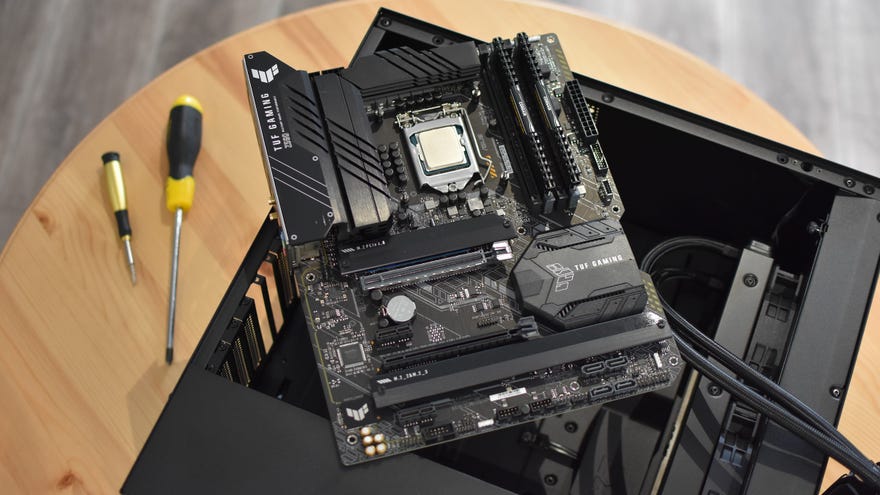
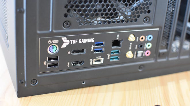
Step 1:Check whether your motherboard’s I/O shield – that’s a metal plate that surrounds its onboard USB, audio, and network ports – is integrated, or separate. The TUF Gaming board you can see in these photos has a handy integrated one, so we don’t need to do anything, but if there’s a separate shield in your box you’ll need to pop this into the case before the motherboard itself . Simply press it down firmly into the big rectangular void at the rear of the case, from the inside facing out, until it clicks into position.
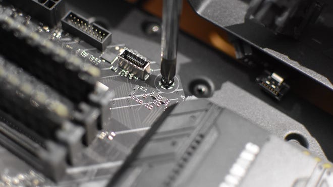
Step 2:Lay the case down on its side, with no cables laying around in the motherboard tray. Then, take your motherboard and gently lay it down inside this main chamber. The screw standoffs inside the case should line up with the holes on the motherboard, but if they don’t, just take the mobo back out, unscrew any misplaced standoffs, and reposition them. The tray will usually have a few empty holes into which you can move these standoffs.
Assuming everything lines up, double check that the motherboard is laying flat, that the I/O ports line up with the shield (if it came separate), and that there are no trapped cables underneath. If you’re good to proceed, take the small screws that came with your chassis and start screwing them into the standoffs. If your chassis came with several sizes of small screw, its manual will tell you which size you need for motherboard mounting.
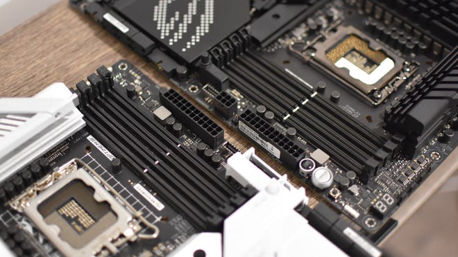
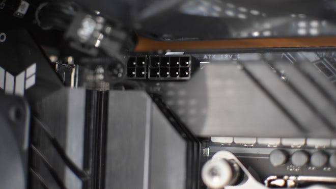
Step 3:With these screws fastened, the motherboard should now sit secure inside the case, but leave it lying down for now because it’s time to start making connections. Let’s start with the PSU cables. There will always be one eight-pin CPU power connector at the top-left of the board and a hefty 24-pin connector over on the right edge, so find grab the matching power cables and plug these in. Some mobos may have a secondary four-pin or eight-pin CPU power connector next to the main eight-pin header, but you don’t actually need to fill this in unless you intend to perform some seriously ambitious overclocking. Then again, if your PSU happens to supply the requisite extra cable, you may want to plug it in anyway.
Some CPU coolers, especially AIO liquid coolers, may also require a SATA power cable (the ones with the header shaped like a stretched-out capital L). Don’t forget one of those if your cooler needs it.
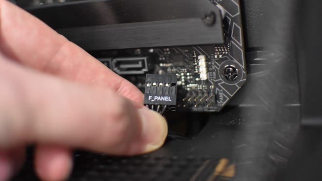
Step 4:The bulk of the other cables you’ll need to connect come from the case’s front panel. These can include cables for any USB and USB-C ports, and/or an HD-Audio cable for mic and headphone jacks, though there will always be a set of very small connectors for the power switch and activity LEDs. These should be carefully attached to a labelled header that’s usually around the bottom-right corner of the motherboard. If you’re lucky, as I was here, they’ll all be merged into one header labelled “Front Panel” or “F_Panel”. If not, they’ll be in a little bouquet of individual connectors, so be sure to place them on the correct pins as per the manual or a diagram on the board itself. These teensy connectors can be fiddly, but your PC won’t work without them.
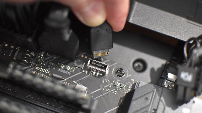
As for the USB connectors, these are normally up on the motherboard’s right edge, while the audio connector should be in the bottom-left corner. Their respective headers will all have different shapes and should be labelled, so don’t worry too much about potentially getting them wrong.
Step 5:Next up, connect the fans. A minority of cases include fan hubs, which are separate modules that allow multiple case fans to plug in, with the hub itself connected to a single header on the motherboard. More likely, however, is that you’ll need to connect the fans directly to the motherboard itself. Case fans can plug into any four-pin SYS_FAN headers available, and don’t worry if the cable appears to have a three-pin connector – these will still work with 4-pin headers. Just use the little plastic fins on the headers to guide the cable onto the pins.
CPU cooler fans are covered in their owninstallation section. These will obviously need to be connected as well, but if you have an AIO cooler with a radiator, it’s better to get that fitted first. That way, you can route the fan cables more easily.
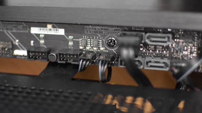
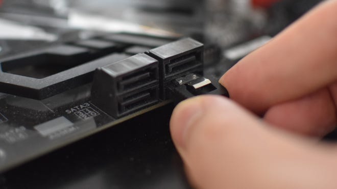
Step 6:If you’re using SATA-connected storage, like hard drives or a 2.5in SSD, it might be helpful to pre-emptively plug in the SATA cable(s) that they’ll need. These cables should be in the box that the motherboard came in, and the ports are typically positioned to the lower-right of the motherboard. Just get them connected at the motherboard’s end for now.